1. Technical background
The production process of the motor core mainly includes stamping, stamping sorting, stacking, and other steps, involving mainstream processes such as riveting, welding, and buckling. Under the processing of these processes, the processing area of the electrical steel sheet often has problems such as deformation, embrittlement, and the formation of a thermal reaction zone, resulting in the deterioration of magnetic properties. Therefore, it is very important to detect the magnetic performance level of the local area of the iron core to evaluate the performance of the iron core and improve its manufacturing technology.
The coil method is currently used as a local magnetic flux measurement method for iron cores, but this method requires drilling holes in the steel plate, which may affect the distribution of magnetic flux density. To avoid this problem, we have newly developed and applied a non-destructive measurement method using a needle probe. This method uses a local magnetic measurement technique combining probe technology (distance between probes: 3.5 mm) and micro H-coil technology (2 mm × 2 mm), which enables non-destructive measurement without damaging the motor core. The local magnetic flux and magnetic field strength of the coated non-oriented electrical steel sheet, which is beneficial to study the influence of stress and strain generated in the core production process on the magnetic properties.
2. Test method
Probe and H-coil. Calculation of the local magnetic flux density of the stator core: that is, the induced voltage between the needle-shaped probes placed in contact with the steel plate surface is equal to the voltage induced by the magnetic flux passing through 1/2 of the closed cross-sectional area under the contact point of the probe. Assuming that the distance between the two probes is 3.5 mm, the magnetic flux density is calculated by the following equation.
Bi = (2/SBi) ∫ eBi dt (i: x,y) (1)
Among them, SBi is the effective area of the probes to detect the magnetic flux, and eBi is the potential difference between the needle-like probes.
Using the induced voltage of the H-coil placed on the steel plate surface, the field strength on the steel plate surface was calculated by the following equation.
Hi= (1/μ0SHiNHi)∫ eHi dt (i: x,y) (2)
Among them, μ0 is the vacuum permeability, SHiNHi is the effective area turns of the H coil, and eHi is the output voltage of the H coil.
Figure 1 is a schematic diagram of the test method used to measure the magnetic flux distribution and magnetic field strength around the weld seam of the motor stator core.

Figure 2 shows the needle probe H-coil and motor drive system. The motor drive system employs a mechanism in which the motor under test is coupled to an external drive motor through a pulley, and the motor under test rotates at a specified speed. The tested motor is a permanent magnet synchronous motor (stator: 18 slots, rotor: 12 poles), with a stator diameter of ϕ 200 mm, a rotor diameter of ϕ 114 mm, and a stack height of 30 mm. The joints between the stator layers are fixed by welding.

3. Result analysis
Figure 3 shows the magnetic flux density distribution measured with the probe technique. The value of each measurement point is the maximum absolute value of the magnetic flux vector during one revolution of the rotor. A point of low magnetic flux density was detected at the rear of the stator core near the weld.
Figure 4 shows the field strength measured by the H-coil. As in the case of magnetic flux density distribution, the value of each measurement point is the maximum absolute value of the magnetic field intensity vector when the rotor rotates one revolution, and the magnetic field intensity distribution at the rear of the stator core near the weld is different from that at the non-welded portion.

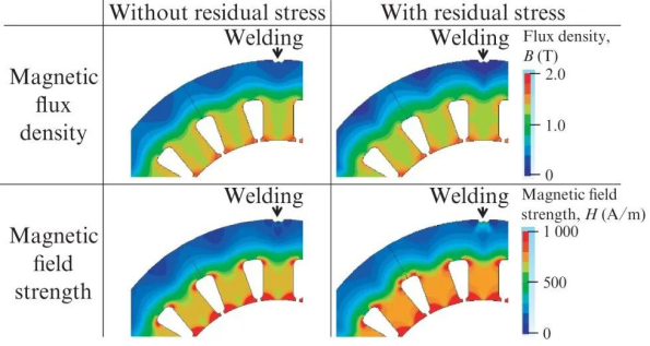
Figure 5 shows the numerical analysis results of the magnetic flux density distribution and the field strength distribution. In this analysis, the influence of welding on the magnetic properties of the stator core is investigated through a coupled analysis of the thermal structure and the electromagnetic field. When the influence of stress is not considered, neither the magnetic flux density distribution nor the magnetic field intensity distribution around the weld changes. In contrast, when considering the residual stress due to welding, deterioration around the weld was found, and a distribution similar to the measured values of magnetic flux density and magnetic field strength was obtained.


